Stepper Motors Demystified: A Comprehensive Guide to Understanding Stepper Motor Theory
Introduction
Stepper motors are a type of electromechanical device that convert electrical pulses into precise mechanical movement, making them a popular choice for a wide range of applications, from robotics and automation to 3D printing and CNC machines. However, understanding the principles and theory behind stepper motors can be a daunting task for those who are new to the field.
Our comprehensive tecahnical guides on steppers aim to demystify stepper motors by providing a clear and concise explanation of their operation, types, and applications, as well as practical tips and best practices for designing, selecting, and using stepper motors effectively.
Motors convert electrical energy into mechanical energy. A stepper motor converts electrical pulses into specific rotational movements.
The movement created by each pulse is precise and repeatable, which is why stepper motors are so effective for positioning applications.
Basics
Permanent Magnet stepper motors incorporate a permanent magnet rotor, coil windings and magnetically conductive stators. Energizing a coil winding creates an electromagnetic field with a north pole and a south pole as shown in Figure 1. The stator carries the magnetic field. The magnetic field can be altered by sequentially energising or “stepping” the stator coils which generates rotary motion.
Figure 2 below illustrates a typical step sequence for a two-phase motor. In Step 1 phase A of a two-phase stator is energised. This magnetically locks the rotor in the position shown, since unlike poles attract, When phase A is turned off and phase B is turned on, the rotor rotates 90°clockwise.In step 3, phase B is turned on but with the polarity reversed from Step 1, this causes another 90°rotation. In Step 4, phase A is turned off and phase B is turned on, with polarity reversed from Step2. Repeating this sequence causes the rotor to rotate clockwise in 90°steps.
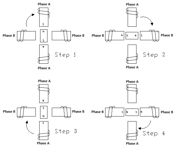
Figure 1: Magnetic field created by energising a coil winding
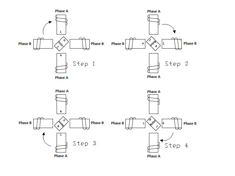
Figure 2: A typical step sequence for a two-phase motor
The stepping sequence illustrated in Figure 2 is called “one phase on” stepping. A more common method of stepping is “two phase on” where both phases of the motor are always energised. However, only the polarity of phase is switched at a time, as shown in Figure 3. With two-phase-on stepping the rotor aligns itself between the “average” north and “average” south magnetic poles. Since both phases are always on, this method gives 41.4% more torque than “one phase on” stepping.
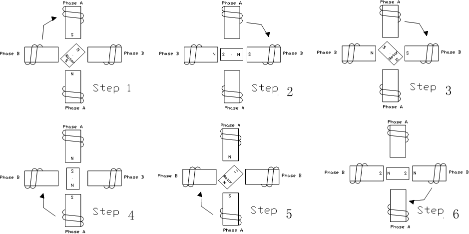
Figure 3: “Two phase on” stepping sequence for two-phase motor
Half Stepping
The motor can also be “half stepped” by inserting an off state between transitioning phases. This cuts a stepper’s full step angle in half. For example, a 90°stepping motor would move 45°on each half step, Figure 4. However, half stepping typically results in a 15%-30% loss of torque depending on step rate when compared to the two phase on stepping sequence. Since one of the windings is not energized during each alternating half step there is less electromagnetic force exerted on the rotor resulting in a net loss of torque.
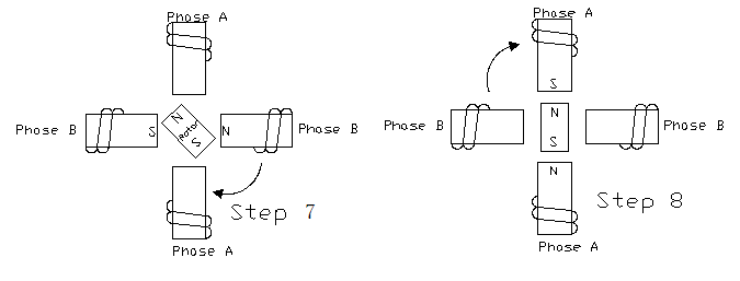
Figure 4: Half-stepping-90°step angle reduced to 45°with half-stepping
Bipolar Winding
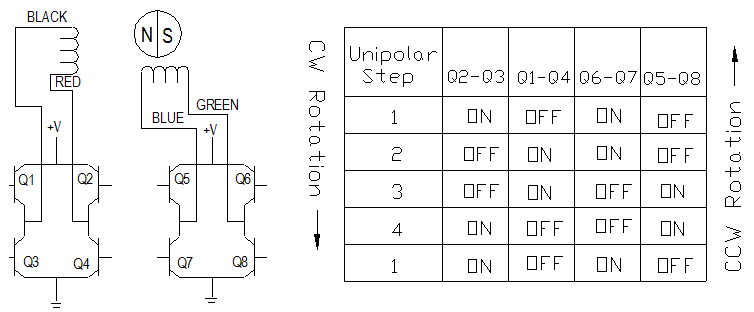
Figure 5: Wiring diagram and step sequence for bipolar motor
The two-phase stepping sequence described utilises a “bipolar coil winding.” Each phase consists of a single winding. By reversing the current in the windings, electromagnetic polarity is revered. The output stage of a typical two phase bipolar dive is further illustrated in the electrical schematic diagram and stepping sequence in Figure 5. As illustrated, switching simply reverses the current flow through the winding thereby changing the polarity of that phase.
Unipolar Winding
Another common winding is the unipolar winding. This consists of two windings on a pole connected in such a way that when one winding is energised a magnetic north pole is created, when the other winding is energised a south pole is created. This is referred to as a unipolar winding because the electrical polarity, i.e. current flowing from the drive to the coils is never reversed. The stepping sequence is illustrated in Figure 6. This design allows for a simpler electronic drive. However, there is approximately 30% less torque available compared to a bipolar copper as compared to a bipolar coil.
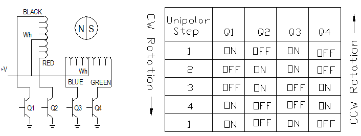
Figure 6: Wiring diagram and step sequence for unipolar motor
What's Next...
Now that you have a solid understanding of stepper motor theory and operation, it's time to dive deeper into the process of selecting the right stepper motor for your specific application.
Please refer to A Selection Guide for Stepper Motors page which is the perfect follow-up to our comprehensive technical guide, as it provides a step-by-step approach to choosing the ideal stepper motor based on key factors such as torque, speed, resolution, and driver selection.